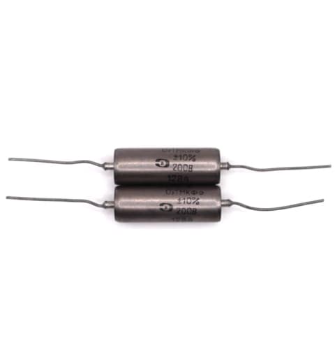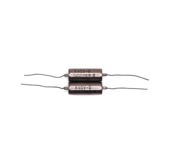


K40Y-9 capacitors come in a lot of variations — capacitances from 470 pF to 1 µF, voltages from 200 V to 1000 V — and those versions are not all the same size. I get asked what dimensions to expect fairly often, so here is how to look them up for any version.
It is simpler than it looks.
The short version: read the capacitance and rated voltage printed on the body, find that pair in the K40Y-9 datasheet table, and read the D and L columns — D is the body diameter, L is the body length, both in mm. The wire leads add 25 mm at each end and are 0.6, 0.8 or 1 mm thick. For example, a 0.1 µF 200 V part is 10 × 28 mm with 25 mm of wire on either side, so 78 mm end to end.
Let’s go through the drawing.
Start with capacitance and rated voltage
The size table is indexed by two columns: nominal capacitance in µF and rated voltage in V. Both are needed, because the same capacitance in a higher-voltage version gets a bigger case. 0.1 µF is 10 × 28 mm at 200 V, 14 × 30 mm at 400 V, and 16 × 30 mm at 630 V — the same capacitance in three noticeably different cases.

The table as printed: the whole 200 V block, with the 400 V block starting at the bottom of the page. One reading habit is worth picking up straight away — where a single D or L figure is centred across several capacitance rows, it applies to every row it spans, which is why 0,047 and 0,068 both read D 10.
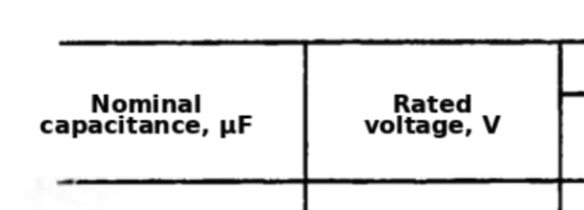
The two columns the lookup starts from, at the head of the datasheet size table.
Both values are printed on the capacitor itself, so no measuring is required to look them up.
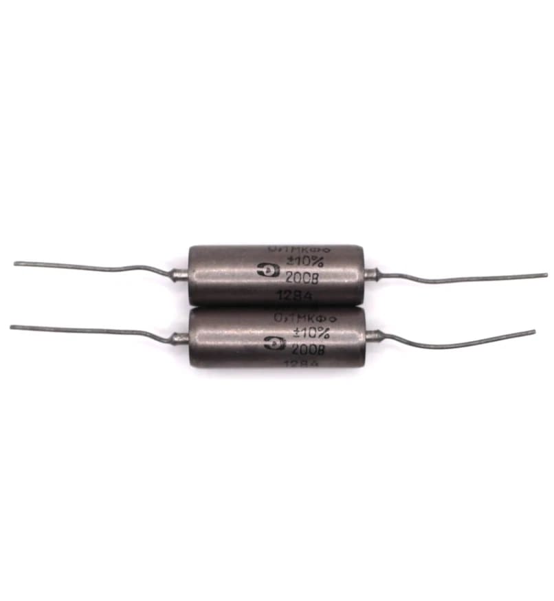
Everything needed for the lookup is on the body: «0,1МКФ» is 0.1 µF, «200В» is the rated voltage. The 12 84 is a December 1984 date code — the Soviet markings guide covers those.
Body diameter: D
D is the outside diameter of the sealed metal case, measured across the cylinder in mm. The wire leads are not part of it.
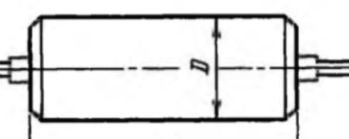
The D arrow spans the metal body and stops at the case wall, which is what makes it a body measurement rather than an overall one.
Across the whole series D runs from 5 mm on the smallest 200 V values up to 20 mm on the largest, and it grows with both capacitance and voltage. For a 0.1 µF 200 V K40Y-9 the table gives D = 10 mm.
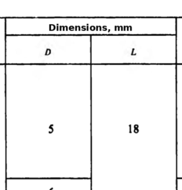
Both size columns sit under one «Dimensions, mm» heading, D first and L second. The top row is the 5 × 18 mm case that covers the smallest 200 V values.
Body length: L
L is the length of the metal case, from one end to the other, again with the leads excluded. Across the series it runs from 18 mm to 62 mm.
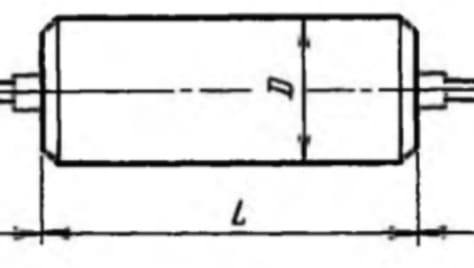
The L line runs between the two case ends and stops where the leads begin, so the 25 mm of wire at each end is counted separately.
D and L do not move together, so the diameter alone does not give the footprint. At 200 V, four different capacitances share D = 10 mm and differ only in length: 0.047 and 0.068 µF at 22 mm, 0.1 µF at 28 mm, and 0.15 µF at 35 mm. For that 0.1 µF 200 V part the table gives L = 28 mm, so the documented body size is 10 × 28 mm.
Lead diameter: Ø
The diameter callout on the drawing reads Ø 0,6 — 0,8; 1. That is a list of the three lead-wire diameters used in the series: 0.6, 0.8 and 1 mm. It is not a tolerance range.
The datasheet does not say which of the three diameters goes with which capacitance and voltage row, and the spread matters in practice — a 0.8 mm hole will not take a 1 mm lead. If the PCB hole size is tight, measure the leads on the actual capacitor before drilling.
Lead length: 25 mm
The 25 mm figure appears twice on the drawing, once at each end, measured from the end of the case to the end of the wire. An untrimmed capacitor therefore has 25 mm of lead available on each side.

Where the 25 mm is measured from: the end of the case, not the middle of the body. The stacked figures above the wire are the three available lead diameters.
Stock that has been in storage for forty years often arrives with the leads already bent. The 25 mm is the length of a straight, untrimmed lead, so where lead reach actually matters, straighten and measure what arrived rather than assuming the full 25 mm is usable.
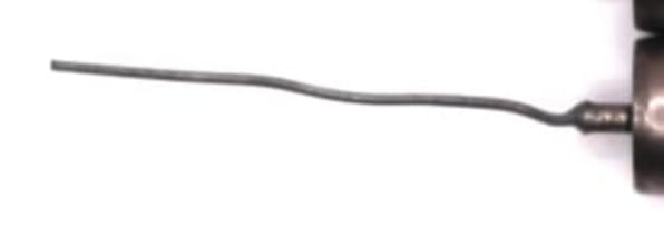
The same lead on a real capacitor: nothing trimmed, but a bend picked up in storage. Until it is straightened out, the reach is shorter than the 25 mm on the drawing.
Putting the dimensions together
For a 0.1 µF 200 V K40Y-9:
- Body diameter D: 10 mm
- Body length L: 28 mm
- Lead length: 25 mm at each end
- Overall straight length: 28 + 25 + 25 = 78 mm
The same lookup run on a few of the values usually in stock shows how far the case size moves across one series. Mass is worth noting for anything hanging off a turret board or tag strip rather than sitting on a PCB:
- 470 pF 200 V — D 5 mm, L 18 mm, 2.5 g, 68 mm overall
- 0.01 µF 630 V — D 8 mm, L 21 mm, 5 g, 71 mm overall
- 4700 pF 1000 V — D 10 mm, L 22 mm, 8 g, 72 mm overall
- 0.1 µF 200 V — D 10 mm, L 28 mm, 9 g, 78 mm overall
- 0.068 µF 630 V — D 14 mm, L 30 mm, 17 g, 80 mm overall
Two pairs in that list show why the voltage column cannot be skipped. The 4700 pF 1000 V capacitor holds less than half the capacitance of the 0.01 µF 630 V one and still needs a larger case, and the 0.068 µF 630 V is larger again than the 0.1 µF 200 V while holding less. Voltage drives the case size as much as capacitance does.
The datasheet table lists the remaining values in the same layout at 200, 400, 630 and 1000 V.
Bottom line
The datasheet table is all it takes: match the capacitance and rated voltage printed on the body, read D and L, and allow 25 mm for each untrimmed lead.
If any questions are left about a particular value, do not hesitate to ask us.
Thank you for reading!
References used:
- K40Y-9 / K40U-9 datasheet — dimension table, mechanical drawing and ratings