

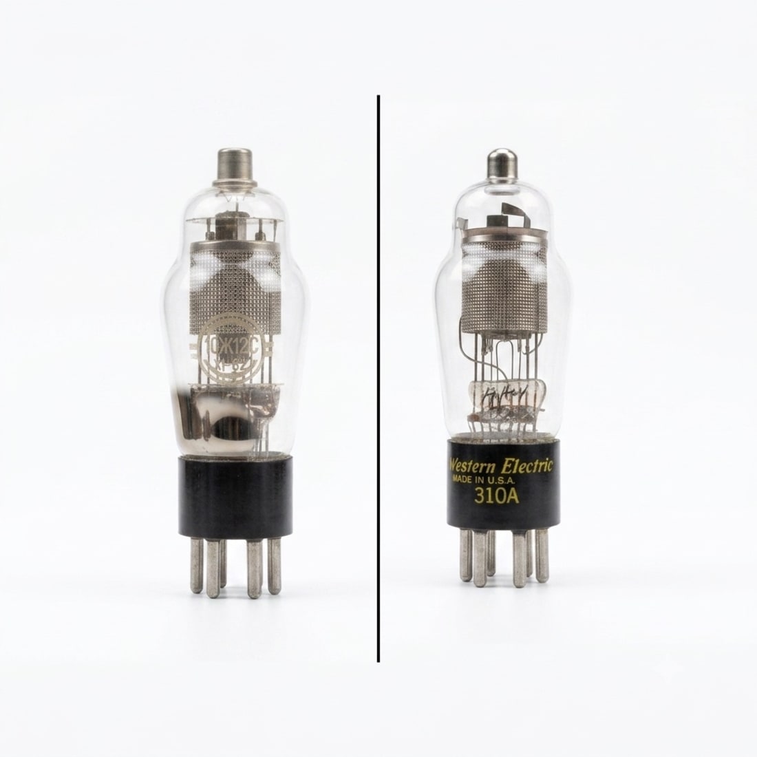
The short answer: the Soviet 10Ж12С, also written as 10Zh12S or 10J12S, can stand in for a Western Electric 310A in some circuits, but not in all of them. Check the operating point before fitting one.
It is a close analogue. Both tubes have a 10 V, 0.32 A heater, the same six-pin layout and a top-cap control-grid connection.
The important difference is plate dissipation. The 10J12S is rated at 1.9 W, while the Western Electric General Bulletin tables rate the 310A at 2.5 W. A 10J12S may work safely in a 310A circuit that stays within the Soviet tube’s limits, but it is not a universal drop-in replacement.
The main ratings
| Rating | 10J12S / 10Ж12С | Western Electric 310A |
|---|---|---|
| Heater | 10 ± 0.7 V, 0.32 A | 10 V, 0.32 A |
| Published control-grid bias | −3 V | −3 V |
| Screen-grid voltage | 135 V nominal, 180 V maximum | 135 V in the published operating data, 180 V maximum |
| Maximum plate voltage | 250 V | 250 V in the factory datasheet; 275 V in the General Bulletin tables |
| Maximum plate dissipation | 1.9 W | 2.5 W in the General Bulletin tables |
| Maximum screen-grid dissipation | 0.4 W | 0.4 W in the General Bulletin tables |
| Maximum cathode current (plate plus screen) | Not stated; nominal 5.5 ± 1.5 mA plate and 1.05 ± 0.55 mA screen | 10 mA |
| Maximum heater-to-cathode voltage | 150 V | 150 V |
| Transconductance in published data | 1.85 ± 0.25 mA/V | 1800 µmhos, or 1.8 mA/V |
| Plate resistance in published data | 500 kΩ | 750 kΩ in the 1946 bulletin, 650 kΩ in the later edition |
The heater and screen-grid ratings are a close match. The lower plate-dissipation limit is the main reason to be careful.
The two Western Electric documents do not agree on every limit. The factory datasheet caps the plate at 250 V, while the General Bulletin tables allow 275 V. The 10J12S limit is 250 V either way, so the lower figure is the one to compare against. The factory datasheet also gives no plate-dissipation figure at all; its 2.5 mA screen-grid current limit is a separate rating and not the 2.5 W above.
Voltage alone is not enough. At the DC operating point, plate dissipation is approximately plate-to-cathode voltage multiplied by plate current. Both values need to stay within the 10J12S ratings. Screen-grid dissipation, cathode current and the bias arrangement also need checking.
The transconductance figures are close. The published plate resistance is not, and a lower plate resistance changes the gain and the load the following stage sees, so a substitution that clears every rating can still change how the stage performs.
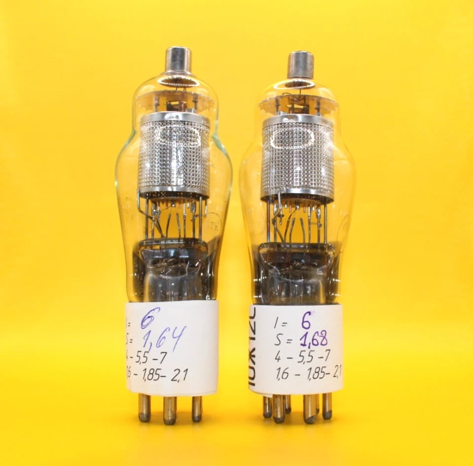
A matched pair of Svetlana 10J12S pentodes. The top caps are visible, and the six base pins show below the handwritten test labels.
Does the pinout match?
Yes. The Soviet drawing and Western Electric basing diagram 32 show the same electrode layout when viewed from the bottom:
| Connection | Pin |
|---|---|
| Heater | 1 |
| Plate | 2 |
| Screen grid (g2) | 3 |
| Suppressor grid (g3) | 4 |
| Cathode | 5 |
| Heater | 6 |
| Control grid (g1) | Top cap |
The 10J12S drawing also shows the tube envelope tied to pin 4 alongside the suppressor grid; the Western Electric diagram marks no such connection. This is a six-pin base, not the familiar eight-pin octal base used by tubes such as the 6SN7.
That shared pin matters in one case. Western Electric brought the 310A suppressor grid out to its own terminal so it could take a separate input, and the datasheet publishes modulator characteristics for that use. On the 10J12S the same pin also carries the envelope, and the Soviet data gives a nominal suppressor-grid voltage of 0 V. In an ordinary voltage-amplifier stage, with the suppressor at 0 V, the shared pin causes no trouble. In a stage that drives or biases the suppressor away from 0 V, the two tubes are not interchangeable.
Western Electric calls for a standard six-contact socket, preferably the 144B, which is also the socket listed for the 310A in the General Bulletin tables. Whatever socket is used, check the bottom-view numbering before wiring it and keep the top-cap lead clear of the other connections.
What to check before replacing a 310A
- The heater supply must provide 10 V at about 0.32 A.
- Plate voltage must not exceed 250 V.
- Plate dissipation must stay at or below 1.9 W.
- Screen-grid voltage and dissipation must stay within 180 V and 0.4 W.
- Plate current and screen current should sit near the nominal 5.5 mA and 1.05 mA rather than at the 10 mA total the 310A allows.
- The suppressor grid should sit at 0 V, since pin 4 also carries the envelope on the Soviet tube.
- The socket wiring and top-cap connection must match the diagrams.
The available Svetlana 10J12S pair is matched and tested on an L3-3. This short L3-3 guide explains what that test checks.
Bottom line
The 10J12S is a sensible 310A alternative when the circuit stays within the Soviet tube’s ratings. The heater, six-pin layout and top-cap connection match, but the lower 1.9 W plate-dissipation limit must be respected.
If the circuit runs a 310A above 250 V or 1.9 W, do not make the substitution without changing the operating point.
Thank you for reading!
References used:
- 10J12S / 10Ж12С technical data and pinout — ratings, electrode connections and the dimensional drawing, compiled there from Broide’s Электровакуумные приборы (Госэнергоиздат, 1956) and the Приемно-усилительные лампы catalogue (Машприборинторг, 1970)
- Western Electric 310A factory datasheet — heater, capacitances, basing, socket and limiting conditions
- Western Electric Electron Tubes General Bulletin, 1946 — 310A row in the General Purpose Tubes table
- Western Electric Electron Tubes General Bulletin, later edition — same table plus basing diagram 32
